
Repairing an Omni-Directional Wheelchair
Table of Contents
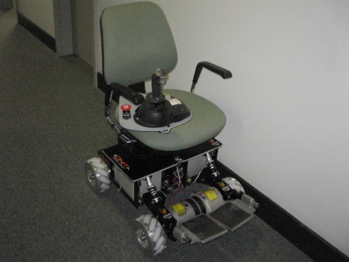
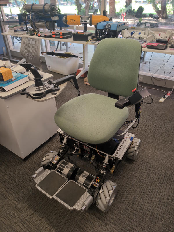
From February to May, I've been interning for the Renewable Energy Vehicle (REV) project at the UWA. I was originally tasked to be a helper for the Autonomous Shuttle Bus but due to the job description mainly involving data collection from driving the bus and not involving much engineering, my supervisor had thought my expertise would be more useful elsewhere. So I was relocated to one of their other projects which had been sitting, collecting dust. This happened to be the Omni-Directional Wheelchair. This is a wheelchair that was designed in 2006 as part of a students honour thesis. A lot of the specifications are currently outdated but the main functionality remains the same. It is a compact wheelchair capable of supporting up to 100kg of weight, it has custom-built Mecanum wheels that enable movement in any direction including lateral and rotational movements, and it operates fully from two car batteries. By the end of this blog post, you will learn the process of how I repaired the wheelchair back to a fully functioning and the challenges I had to overcome along the way.
What Happened?
Sometime last year, the wheelchair was being used for a demo for new students and it suddenly stopped working. I wasn't given much detail on how this happened but apparently it just lost power during the demo. My job was to get this back to its normal operation. I was advised by my supervisor that they had replaced the batteries and all the fuses but it still didn't operate. So, what do we do now?
Replacing the Micro-controller
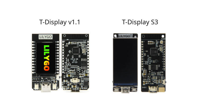
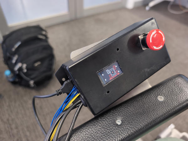
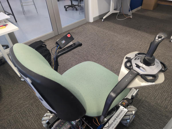
On the left armrest of the wheelchair is a box that contains the main internals that control and operate the wheels. The old system was running a Lilygo T-Display v1.1 wired to a USB Host Shield designed for an Arduino Uno through a custom PCB. A USB joystick was mounted to the right armrest and was plugged into the USB Host Shield. This joystick is was in control of operating the wheelchair motors. The ttgo was then wired to a Sabertooth 2x32 dual motor controller which was in charge of operating each wheel. My supervisor instructed me to replace the current system with a new Lilygo T-Display S3, that way we wouldn't need the bulky USB Host Shield because the S3 has built-in USB Host Mode that we can utilise with the joystick. I already had the Arduino code that was on the original ttgo so... should be an easy fix right?
Somehow not an Easy Fix...
After multiple weeks of trying to get the T-Display S3 working in USB host mode, I ended up giving up as this had been proven to be more difficult that I thought. In theory, it should be as simple as uploading USB Host Mode code to the S3 and plugging in a device like a keyboard or mouse. But no matter what I did, the USB device that I would plug in just wouldn't connect. I ended up having a long conversation with someone on the Arduino forum and he concluded that from reading the schematic, the reason is wasn't working was because the T-Display S3 was not outputting any voltage through the USB port. They said that there is a schottky diode that blocks the voltage from being sent over the USB port. Other users on the T-Display S3 git repo were also having issues saying they couldn't get USB host mode to work. So what do I do now?
Re-Replacing the Micro-controller
Well if I can't get the new S3 working, I guess I'll try and get the old ttgo working instead. The old ttgo T-Display v1.1 was still running the previous Arduino firmware that used to operate the wheelchair. The only problem was, when the joystick was plugged into the USB Host Shield attached to the ttgo, nothing would happen. I tried plugging the joystick into my laptop to see if it came up as a USB device but it didn't appear at all. So I concluded it must be faulty. There happened to be a spare joystick lying around in the lab that appeared as a USB device when I plugged it into my laptop. So I thought if I plug in a working joystick into the USB shield, it should work... right? Turns out it didn't. Okay... maybe there's something wrong with the USB Host Shield then?
Diagnosing the USB Host Shield
Because I couldn't get any sort of connection from the USB Host shield with the T-Display v1.1, I decided I should try connect it to a generic ESP32-WROOM-32 that I had lying around my house. The USB Host shield that I had on hand happened to have no documentation about it on the internet whatsoever. The closest thing I could find was a Keyestudio USB Host Shield that looked remotely close to what I was using.
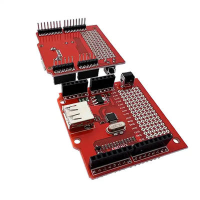
This was somewhat helpful although I didn't know what each GPIO pin was specified for because the board I had did not label any of the GPIO pins. Because this board is supposed to be a plug and play replacement for the Arduino Uno, I had to figure out what each pin did by looking at the pinout for the Arduino Uno. My assumption was that this host shield would be able to work with the USB Host Shield 2.0 library. The README for the library has instructions on how to wire up an ESP32 with the USB Host shield.
ESP32 is supported using the arduino-esp32
GPIO5 : SS, GPIO17 : INT, GPIO18 : SCK, GPIO19 : MISO, GPIO23 : MOSI
After referring to an Arduino Uno's pinout to figure out which pins on the USB Host Shield were what, I was finally able to wire up the board to an ESP32. When I went to run a quality control test on the board to see if it operates, I was able to pass all the tests... except for the final one. The test got stuck on "Waiting for USB Connection...", even after plugging in multiple devices. So, I guess the USB Host shield is also faulty then?
Joystick and USB Host Shield Faulty... So What Now?
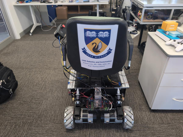
Both the joystick and the USB Host shield seem to be faulty, so how am I supposed to get the wheelchair operating again? Mind you, my supervisor told me that they would like this wheelchair to be ready in time for Open Day so high school students can come see the cool projects that the robotics lab have been working on over the years. And it also turns out that Open Day happens to be only in a couple days!!!

So You're Screwed? Not Exactly...
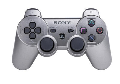
After having at look at the previous code on the wheelchair, it seemed to have some logic to operate it with a PS3 controller. The controller happened to be sitting next to the wheelchair with a label "Omni-Directional Wheelchair". So maybe the controller can connect to the ttgo? After charging it and turning on the controller for pairing, the display on the ttgo reacted! The display shows a bitmap of the wheelchair along with 4 number variables that display the value that is being sent to each wheel. If I moved the left analog stick around, the values for each wheel would change. Although, the wheelchairs wheels were not reacting to this movement. I feel really close now. We just have to get the serial communication between the ttgo and the Sabertooth and then we will have a functioning wheelchair. After some diagnosing, it seemed there was a faulty wire between the Sabertooth and the ttgo, and after replacing that wire, the wheels were now moving!

Bringing the Wheelchair Back To Its Original Self
So the wheelchair now partially works. You can operate it using the PS3 controller and all the main functionality is there. However, the joystick and the USB Host Shield still do not work which means you have to sit with a controller on your lap instead of using the joystick that is bolted into the right arm rest.
Replacing the Joystick
A couple weeks pass, and a new replacement joystick arrives for me to replace. The joystick is a Logitech Extreme 3D Pro. The wheelchair in the past has used different joysticks but the most recent iteration has used this one.

I unbox the joystick and try to plug it into the USB Host Shield hoping that it would work out of the box, but still no luck. What was good news though is that the joystick was able to connect to my laptop and I am able to read the inputs so I know that it works. The previous joystick would not appear on any device no matter what it was plugged into. I inform my supervisor that it could possibly be a faulty USB Host Shield, so we order the same part to be replaced.
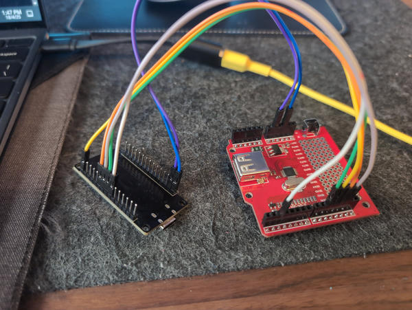
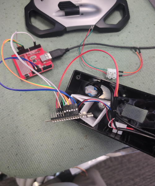
Replacing The USB Host Shield
Shortly after a couple days, the new USB Host Shield arrives. I open its packaging and connect it to the ttgo. The ttgo is connected to a blank PCB which has the wiring and header pins to connect the both boards together. I connect all the parts together and plug in the joystick excepting it to fully operate as it used did. And to my surprise, it still was not able to connect to the ttgo.
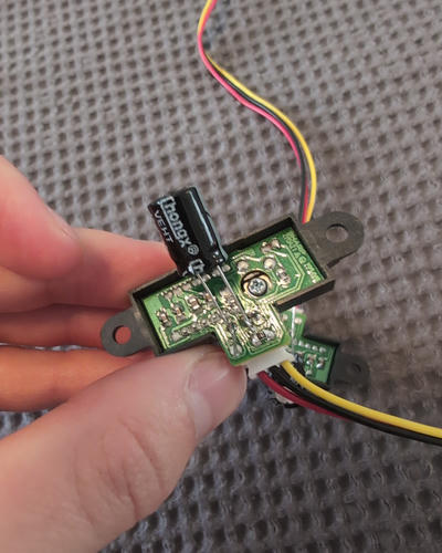
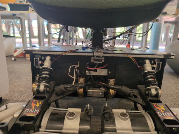
At this point, I am dumbfounded. How is this not able to work? My supervisor has told me this worked in the past with these components and wiring so how is it not able to work now? I do a bit of reading with the past history of the wheelchair and I find that it looks like the previous iterations of the joystick functionality used to worked over Serial. These images below show the internals of the joystick being stripped and replaced so it could be connected over Serial.
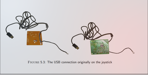
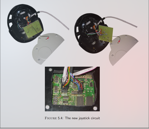
I also found some videos on Instagram of the previous student who had worked on the wheelchair. It looks like from these videos that they had replaced the previous joystick with the Logitech one. My assumption from these images is that they had an Arduino Uno attached to the USB Host Shield which was responsible for reading the joystick inputs and then converting them to serial. And then the ttgo was attached on top of both boards and the serial information from the Arduino Uno was sent to the ttgo.
Because I didn't know this at the time and I was unsure how to re-implement this previous protocol with the hardware I was given, I decided to change it to a more simpler solution and use just the USB Host Shield with the ttgo operating over the USB protocol instead.
Testing USB Host Library with ESP32
The first step was to wire up the USB Host Sheild according to the documentation on the USB Host Shield 2.0 Libraries git page. I wired it up according to there docs and loaded up one of there example Arduino sketches that they had in the repo. Conveniently they had an example sketch that was specifically for my joystick. So I flashed the ESP32 with the le3dp.ino sketch and it worked... well, partially. When the ESP32 boots up for the first few seconds, I am able to get input from the joystick perfectly. But then shortly after, the serial monitor freezes and I no longer receive any input from the joystick. Here is an example of what was happening:
At this moment, I basically had two options. I could test to see if this issue still happens with the ttgo board and hope it works without freezing or I would have to adjust the wheelchair code to account for the freezing.
Forking USB Host Library 2.0 to Work for ttgo T-Display v1.1
Trying to wire the ttgo to the USB Host Shield came with a bit of a challenge. Because the ttgo has a different pin layout to generic ESP32's, some of the exposed pins were missing for me to use. For example, GPIO5 which is used for SS, was not exposed for me to use because it was internally being used for the built-in display.
After doing a bit of research, some user had stated that the SPI pins used to connect external SPI peripherals to the ttgo are the following:
#define PIN_MISO  27  // GPIO27
#define PIN_MOSI  26  // GPIO26
#define PIN_SCK   25  // GIPO25
#define PIN_CS    33  // GPIO33

...
SD.begin(PIN_CS, PIN_MOSI, PIN_MISO, PIN_SCK)
A more detailed discussion of the thread can be found here.
So now I just need to figure out how to use these pins in the library. Because the libraries GPIO pin configuration for its devices are hard-coded and not modular in your Arduino sketches, I had to fork the library and overwrite the original ESP32 SPI pins with the ttgo's. After doing this, I ran the sample le3dp.ino sketch on the ttgo and it worked! Not only did it work, but there was no more freezing on the joystick anymore. I must of had a faulty ESP32 but nonetheless, I am able to read the values of the joystick on the ttgo!
The fork of my USB Host Shield 2.0 library can be found here if you want to connect USB peripherals to your ttgo or you want to see how you can override the hard-coded SPI pins for your ESP32 board.
Refactoring Wheelchair Arduino Code
Old Wheelchair Code
The old wheelchair Arduino sketch for the ttgo receives ASCII hexadecimal input from the Arduino Uno and converts them into integers which are then converted to motor speed values based on the MAX_SPEED. The FrontL, FrontR, BackL and BackR are then sent to the Sabertooth Controller which operates the motors:
// Get Joystick Values
x = getJoystickValue('X'); // X Joystick value received from Arduino Uno
x = mapf(x, xmin, xmax, -1.0, 1.0); // Scale each axis to normalised -1 to +1

y = getJoystickValue('Y'); // Y Joystick value received from Arduino Uno
y = mapf(y, ymin, ymax, 1.0, -1.0); // Scale each axis to normalised -1 to +1

z = getJoystickValue('Z'); // Z Joystick value received from Arduino Uno
z = -mapf(z, zmin, zmax, -1.0, 1.0); // Scale each axis to normalised -1 to +1

t = getJoystickValue('T'); // T Joystick slider value received from Arduino Uno
t = mapf(t, tmin, tmax, 0, 1.0); // Scale each axis to normalised 0 to +1

// Calculate motor speeds
int FrontL = constrain((y + x - z) * MAX_SPEED * t, -MAX_SPEED, MAX_SPEED);
int FrontR = constrain((y - x + z) * MAX_SPEED * t, -MAX_SPEED, MAX_SPEED);
int BackL = constrain((y - x - z) * MAX_SPEED * t, -MAX_SPEED, MAX_SPEED);
int BackR = constrain((y + x + z) * MAX_SPEED * t, -MAX_SPEED, MAX_SPEED);

// Get Joystick Values Helper
int getJoystickValue(char val) {
  // Send a Request to Arduino Uno
  Serial.print(val); Serial.print(": ");
  joystick_serial.println(val);
  delay(2);

  // Collect Reply
  char content[4] = {'\0', '\0', '\0', '\0'};
  char character;
  int j = 0;
  while (joystick_serial.available() || j != 4) {
    character = joystick_serial.read();
    content[j] = character;
    j++;
  }

  // Convert ASCII hex string to int
  int X_VAL = StrToHex(content);
  return X_VAL;
}
New Wheelchair Code
I had to change the previous logic to use the X, Y and Z values received over USB. I used the example Joystick sketch as a base from the USB Host Shield 2.0 Library in-order to receive the integer values of X, Y and Z and incorporated it into the wheelchair code. Because we are eliminating the ASCII Serial bridge and receiving the raw integers straight from the joystick, there was not much work to be done other than removing the ASCII conversion code and using the raw integers as the joystick values. All the code which calculate the motor speeds can remain the same. Here is an example of how it works:
// Joystick Variables
int Xval;   // 0 - 1023
int Yval;   // 0 - 1023
int Hat;    // 0 - 15;
int Twist;  // 0 - 255
int Slider; // 0 - 255
int Button; // 0 - 12 (0 = No button)

Usb.Task();                                                    // Use to read joystick input to controller
JoyEvents.GetValues(Xval, Yval, Hat, Twist, Slider, Button);   // Copies joystick values to user

// Get joystick values
x = Xval; // Use x value received from Joystick
x = mapf(x, xmin, xmax, -1.0, 1.0); // Scale each axis to normalised -1 to +1

y = Yval; // Use y value received from Joystick
y = mapf(y, ymin, ymax, -1.0, 1.0); // Scale each axis to normalised -1 to +1

z = Twist; // Use z value received from Joystick
z = -mapf(z, zmin, zmax, -1.0, 1.0); // Scale each axis to normalised -1 to +1

t = Slider; // Use t value received from Joystick
t = mapf(t, tmin, tmax, 0, 1.0); // Scale each axis to normalised -1 to +1


// Calculate motor speeds
int FrontL = constrain((y + x - z) * MAX_SPEED * t, -MAX_SPEED, MAX_SPEED);
int FrontR = constrain((y - x + z) * MAX_SPEED * t, -MAX_SPEED, MAX_SPEED);
int BackL = constrain((y - x - z) * MAX_SPEED * t, -MAX_SPEED, MAX_SPEED);
int BackR = constrain((y + x + z) * MAX_SPEED * t, -MAX_SPEED, MAX_SPEED);
Joystick Demo
Here is a demo of the joystick operating the wheelchair motors!!!
PIR Sensors
After this was done, my supervisor asked me if I was able to extend the functionality of the wheelchair. He said it would be nice if there was a collision system where the wheelchair would avoid hitting walls if it got too close. He said that there are spare PIR sensors lying around the lab that could be used for the system.
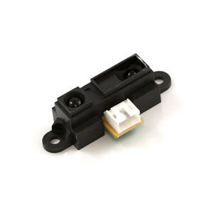
The PIR sensor that I was given was the Sharp GP2Y0A21YK0F Analog Distance Sensor. It's an analog infrared proximity sensor that can measure up to 80cm. The sensor outputs an analog voltage based on how close an object is to the sensor. We can use an equation to convert the voltage to a cm value:

Connecting the PIR sensor to the ttgo
The sensor has a three wire pinout. The red wire takes a 5V input, the black wire is GND and the yellow wire is the data wire which we connect to an analog pin on the ttgo. I then wrote a helper function to convert the analog voltage to a distance in cm's.
// Function to convert analog voltage to distance in cm's
int readSensor(int pin) {
  //int raw = analogRead(pin);
  float volts = analogRead(pin) * 0.0008056640625; // value from sensor * (3.3/4096)
  if (volts < 0.4) return 80;      // too far or no object, return max distance
  if (volts > 3.0) return 10;      // too close, sensor maxed out
  int distance = 29.988 * pow(volts, -1.173);
  return distance;
}
I then wrote some code that prohibited the motor wheels from moving in the direction of the sensor if there was an object close to it. I did this by overwriting the BackL, BackR, FrontL and FrontR values with 0 if they tried to exceed the direction they were going.
Connecting 5 PIR sensors to the ttgo
So now that I know the sensors work, I then proceeded to connect 5 sensors to the ttgo for testing. I put each sensor data wire on an analog pin and then the 5v and GND wires were all shared on the ttgo. However, I ran into some trouble when I started to connect more than a couple sensors. The distance readings started to fluctuate heavily and where not accurate in there readings. This made the collision system basically useless because each sensor would keep triggering the wheelchair to stop because the values kept fluctuating inaccurately.
After some more research, I found that the manufacturer recommends to connect a 10µF capacitor along the sensor power lines to stabilise the voltage readings. So I tried this with a sensor and a breadboard but the readings were still fluctuating. I decided to connect a 100µF capacitor to see if that fixed it and it did...mostly. The distance from each sensor was way more accurate but it was still fluctuating a bit. One of my assumptions was that it could be because I am powering the ttgo over my laptop USB port, and if I connect it to the wheelchair, it will be operating through 5v and GND inputs from the Sabertooth rather than through USB. So I hoped that this would give a more clean power line which as a result makes the sensor voltages more stable and it did.
Creating Collision System in Wheelchair Arduino Code
Now that I know the hardware is going to work, it's time to write the final software. The code first reads every distance value from each sensors analog pin, then once the wheelchair is armed and operating, there is an if statement which compares the sensor distances with a threshold. If it is too close, it zeros only the wheel motor values that would move further in that direction. Then I have some code that colours the wheels on the screen red depending on what sensor is activated:
// Print sensor distance
int front_left_distance = readSensor(FRONT_LEFT);
int front_right_distance = readSensor(FRONT_RIGHT);
int side_left_distance = readSensor(SIDE_LEFT);
int side_right_distance = readSensor(SIDE_RIGHT);
int back_distance = readSensor(BACK);

collisionForward = false;
collisionLeft = false;
collisionRight = false;
collisionBehind = false;

// PSD Sensors
if (started && collisionEnabled) {
  // Prohibit going forward - front sensors
  if (front_left_distance < 68 || front_right_distance < 68) {
    collisionForward = true;
    if (FrontL > 0) FrontL = 0;
    if (FrontR > 0) FrontR = 0;
    if (BackL  > 0) BackL  = 0;
    if (BackR  > 0) BackR  = 0;

    // Print collision message & motor values
    Serial.println("Collision ON! Can't move forward.");
  }

  // Prohibit going left - left side sensor
  if (side_left_distance < 50) {
    collisionLeft = true;
    if (FrontL < 0) FrontL = 0;
    if (FrontR > 0) FrontR = 0;
    if (BackL  > 0) BackL  = 0;
    if (BackR  < 0) BackR  = 0;

    // Print collision message & motor values
    Serial.println("Collision ON! Can't move left.");
  }

  // Prohibit going right - right side sensor
  if (side_right_distance < 50) {
    collisionRight = true;
    if (FrontL > 0) FrontL = 0;
    if (FrontR < 0) FrontR = 0;
    if (BackL  < 0) BackL  = 0;
    if (BackR  > 0) BackR  = 0;

    // Print collision message & motor values
    Serial.println("Collision ON! Can't move right.");
  }

  // Prohibit going backwards - back sensor
  if (back_distance < 60) {
    collisionBehind = true;
    if (FrontL < 0) FrontL = 0;
    if (FrontR < 0) FrontR = 0;
    if (BackL  < 0) BackL  = 0;
    if (BackR  < 0) BackR  = 0;

    // Print collision message & motor values
    Serial.println("Collision ON! Can't move backwards.");
  }

  // Logic to change the wheel colour if collision has been activated.
  bool changed = false;
  if (collisionForward != oldForward || collisionLeft != oldLeft
      || collisionRight != oldRight || collisionBehind != oldBehind) {
    changed = true;
    oldForward  = collisionForward;
    oldLeft = collisionLeft;
    oldRight = collisionRight;
    oldBehind = collisionBehind;
  }

  if (changed) {
    // Decide each wheel’s color
    uint16_t colorFL = (collisionForward || collisionLeft) ? TFT_RED : TFT_WHITE;
    uint16_t colorFR = (collisionForward || collisionRight) ? TFT_RED : TFT_WHITE;
    uint16_t colorBL = (collisionLeft || collisionBehind) ? TFT_RED : TFT_WHITE;
    uint16_t colorBR = (collisionRight || collisionBehind) ? TFT_RED : TFT_WHITE;

    // Change wheel colors
    updateWheels(colorFL, colorFR, colorBL, colorBR);
    drawCollisionWarning(collisionForward || collisionLeft || collisionRight || collisionBehind);
  }
}
Collision Demo
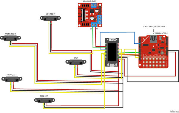
Wiring
If you want to do something similar yourself, I've attached a wiring diagram of how the wheelchair is connected.
Final Result
The wheelchair is finally complete and fully operational. This was a really enlightening experience for me. I have never done any sort of hands-on robotics project before so it was really educational for me and I learned a lot about how these robotic systems work. I've only done simple ESP32 work before and seeing the capabilities of these micro-controllers for real world applications gave me a greater appreciation for what the Arduino/ESP framework can do.
I'd like to thank Thomas Braunl and Kieran Quirke-Brown for giving me the opportunity to work on this project. I hope my contributions to the wheelchair will serve as a valuable asset for future research and practical deployment.
Git Repo's... If You're Interested
Here are some git repo's from myself and others that were used for the wheelchair. Hopefully they can come in useful for people building similar projects:
- USB Host Shield 2.0 Library
- USB Host Shield 2.0 Library ttgo fork
- Arduino Logitech Extreme 3D Library